CSWA Robot Assembly
Complete robot master assembly and modelling with SolidWorks.
📌 Project Overview
This project showcases a complete robotic master assembly modeled in SolidWorks as part of comprehensive preparation for the Certified SOLIDWORKS Associate (CSWA) certification. Special acknowledgment goes to instructor Adan Isais (adnisais), whose excellent CSWA Course and YouTube video tutorials provided the mechanical part designs, 2D engineering drawings, and assembly layouts used to build and model this system.




🧊 Interactive 3D Model Viewer
Explore the master assembly interactively below. To optimize initial page load performance, the interactive 3D viewer is loaded on demand when requested.
Interactive SolidWorks 3D Assembly
Click below to render the full 3D interactive eDrawings model.
📐 Modeling Principles & CSWA Preparation
During the modeling of this 17-lesson robotic master assembly, fundamental CSWA design engineering principles and parametric modeling practices were applied:
- Parametric Modeling & Design Intent: Defined geometric relations prior to driving dimensions, structuring feature trees by independent layers to ensure robustness during design modifications.
- Associative Assembly Hierarchy: Constructed modular sub-assemblies (flexible mechanism joints, rigid links, and structural frames) anchored at origin
(0,0,0)to guarantee accurate mass properties, center of gravity, and moments of inertia. - Mates, Interference & Kinematics: Combined standard, advanced, and mechanical mates to simulate realistic motion ranges, verifying physical clearances via interference detection.
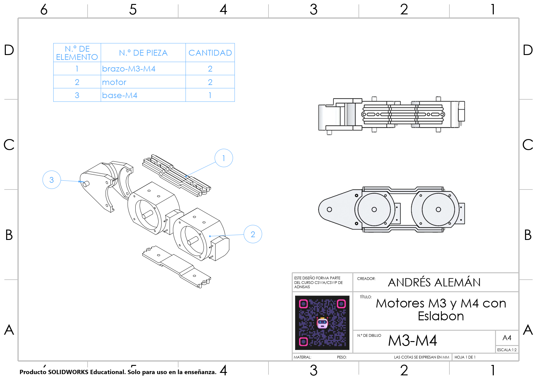
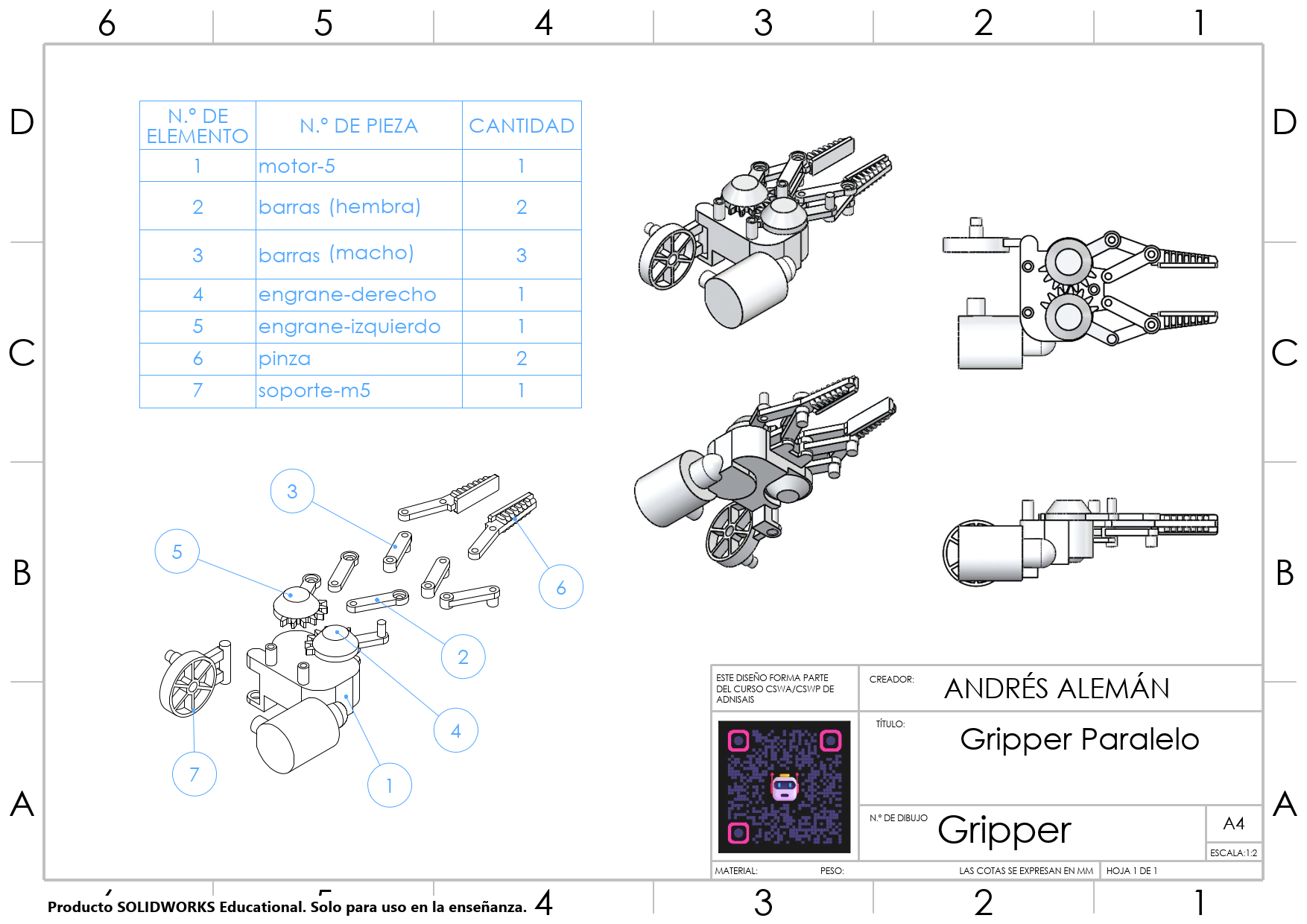
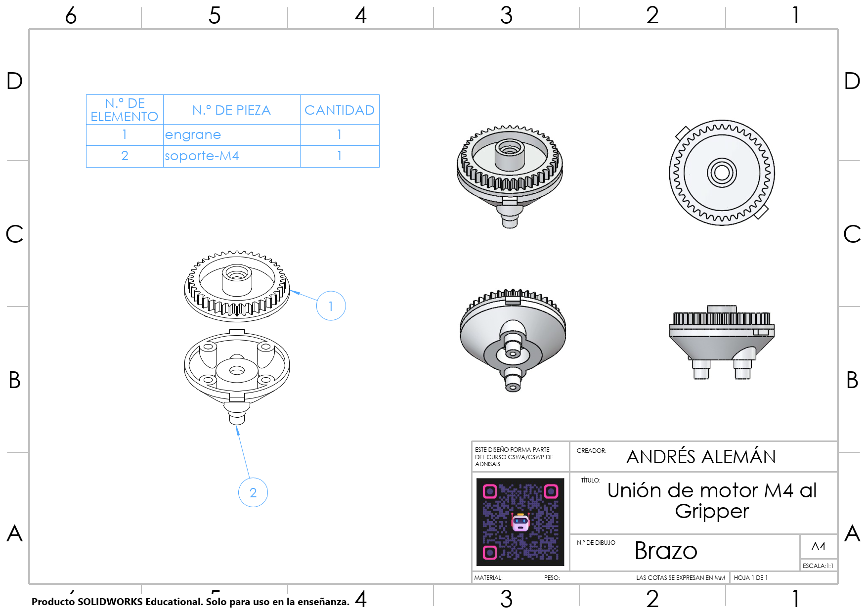
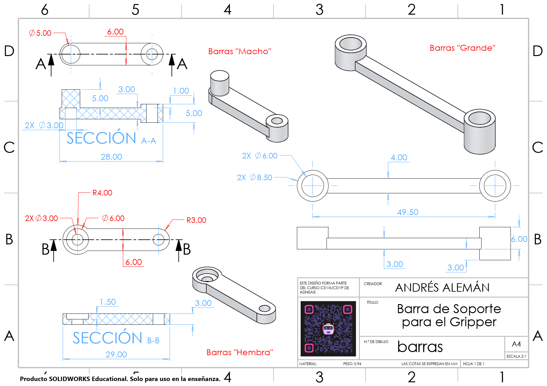
- 2D Engineering & BOM Integration: Generated ISO/ANSI drawing layouts with section views, exploded assembly steps, magnetic balloon callouts, and automated Bills of Materials (BOM).
📜 2D Engineering Drawings & Blueprint Suite
Explore the 8-sheet engineering drawing package below, featuring master assembly BOMs, section views, sub-assemblies, and detailed dimensioning.
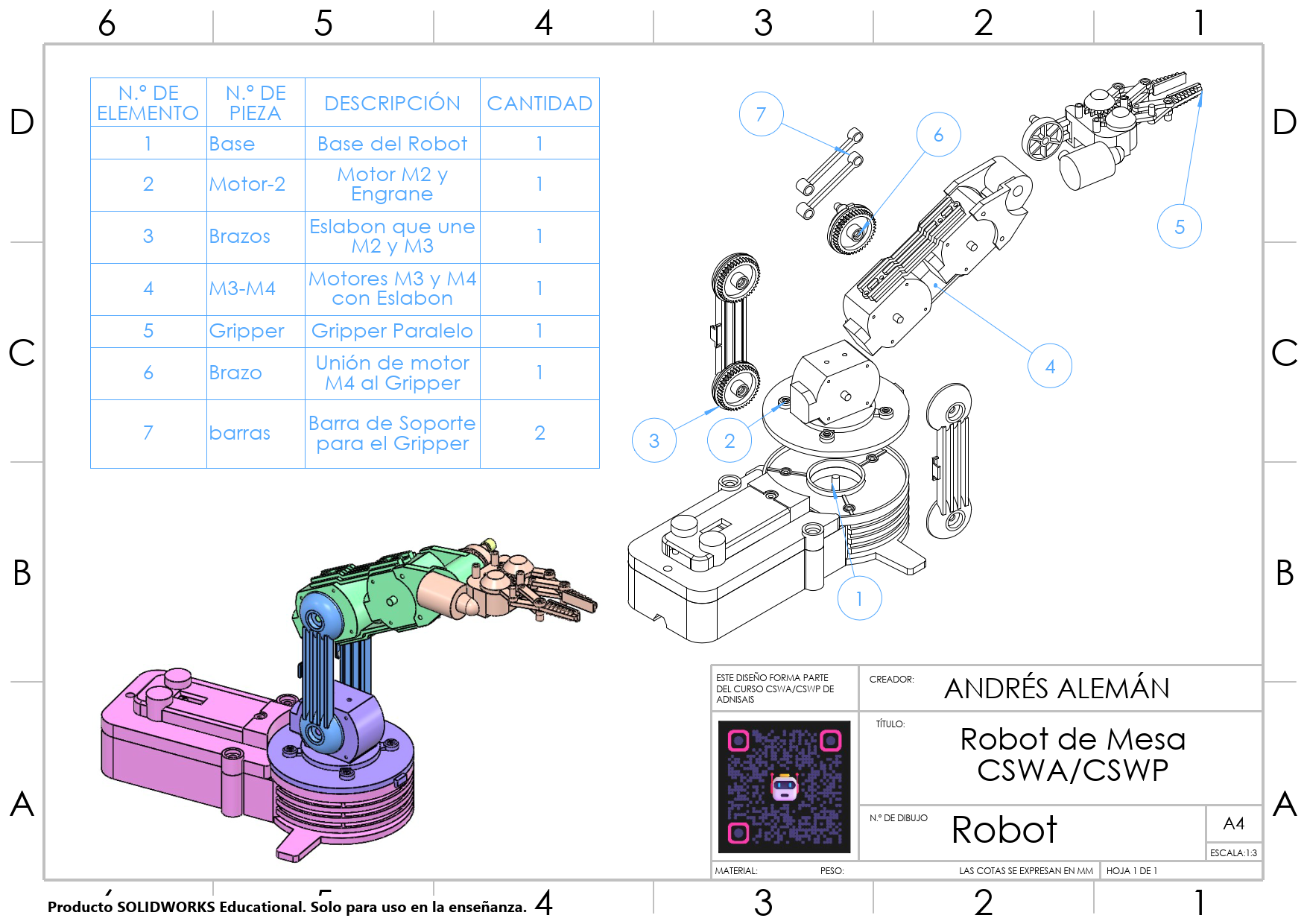
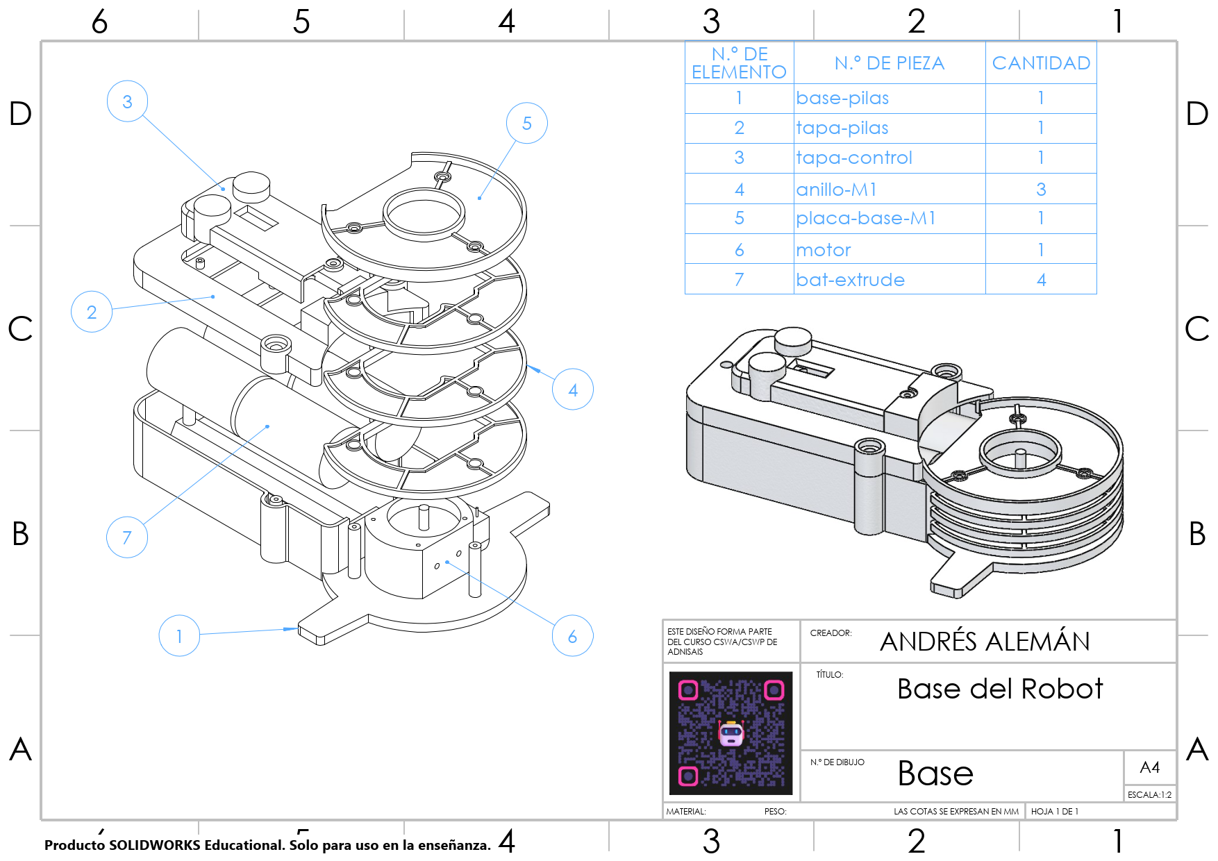
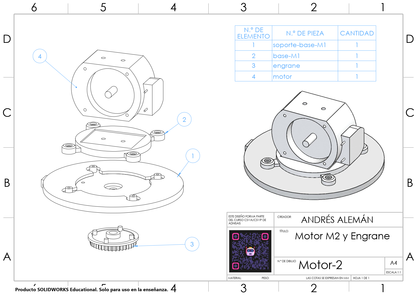
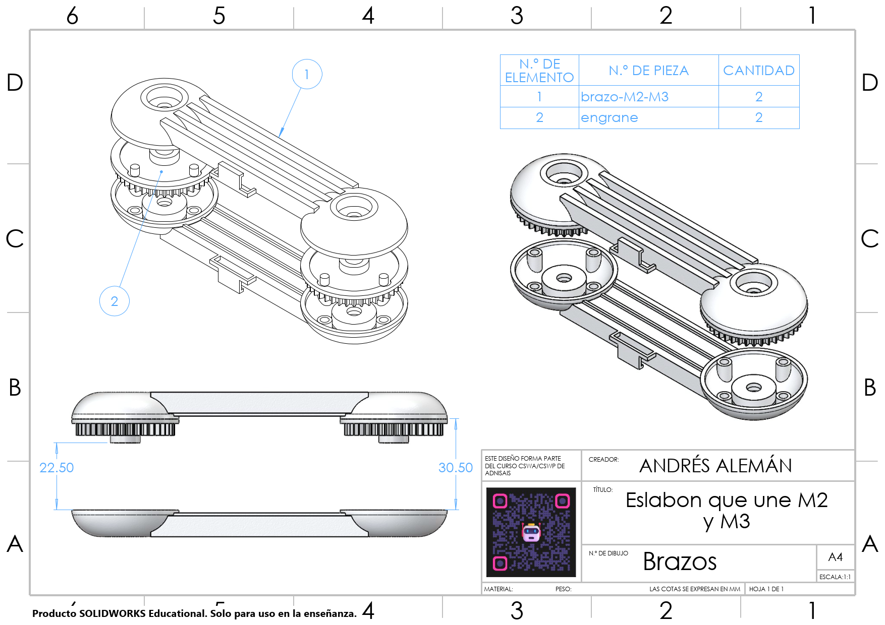
Key Design & Modeling Highlights
- Feature-Based & Associative Workflow: Bi-directional synchronization between parts (`.SLDPRT`), master assembly (`.SLDASM`), and manufacturing drawings (`.SLDDRW`).
- Advanced Geometry & Sweeps: Applied Pierce relations for 3D sweep profiles, thin features for structural shells, and Geometry Pattern features for optimized rebuild performance.
- Assembly Origin Alignment: Strict adherence to origin anchoring `(0,0,0)` for accurate physical property calculations and CSWA evaluation standards.
- eDrawings 3D Web Export: Exported an interactive HTML5 assembly model for web inspection without requiring CAD software installation.